EMI Shielding Cabinet — RF Shielded and TEMPEST Enclosures
Shielded cabinets that limit electromagnetic interference for sensitive equipment and secure rooms.
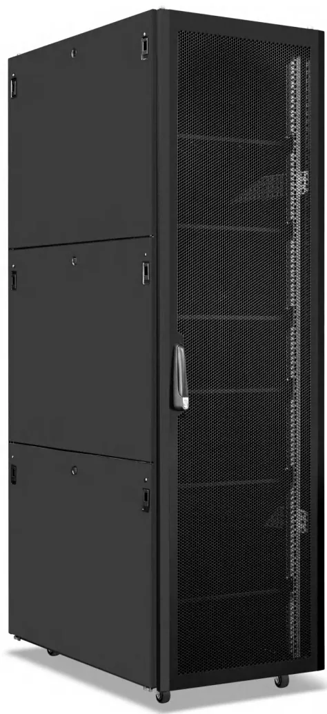
An EMI shielding cabinet uses a steel enclosure, conductive gaskets and filtered power entries to attenuate radio-frequency interference, typically by 20 dB to 100 dB from 10 kHz to 10 GHz. It is used in labs, hospitals, secure rooms and industrial sites where equipment must be isolated from RF noise.
Last reviewed: 2026-11-07
Shielded cabinets are used in defense, government, telecom and test environments where external interference or signal leakage is a concern.
The specification should state the required attenuation range and test method; a cabinet without a test report should not be presented as compliant.
Best for
- Defense and government communications
- Medical and test laboratories
- Projects with a stated EMI requirement
Key specifications
Shielded cabinet reference
| Type | Typical use | Documentation |
|---|---|---|
| RF shielded | Telecom and test rooms | Attenuation test report |
| EMI shielded | Industrial/medical | Model-specific report |
| TEMPEST | Government/defense | Project specification |
How to choose
Define attenuation
State the required dB range and frequency band.
Check the door and filter
The door gasket and power filter are critical to performance.
Require a test report
Match the report to the exact model and configuration.
What an EMI shielding cabinet does
An EMI shielding cabinet is a metal enclosure designed to keep electromagnetic fields out or in. It uses a continuous steel shell, conductive door gaskets, shielded windows and filtered cable entries to reduce radiated interference.
It is used for EMC testing, medical imaging, secure communications, industrial controls and research. The required attenuation depends on the frequency range and the field strength at the site.
Attenuation and frequency range
Typical attenuation is 20 dB to 100 dB, depending on the design, the gasket and the frequency. Low frequencies are harder to shield with thin steel; high frequencies are easier but leak through seams and cable entries.
Specify the attenuation at the frequencies that matter for the project, for example 10 kHz to 1 MHz for power electronics or 100 MHz to 10 GHz for radio and digital equipment. A single dB number without a frequency range is not meaningful.
Doors, gaskets and cable entries
The door is the main leakage path. Use a continuous conductive gasket, a multi-point latch and a flat mating surface. Clean the gasket and the contact surface regularly; dirt and paint reduce the shielding effectiveness.
Cable entries need shielded connectors or filtered feed-throughs. A plain hole for a cable destroys the shielding at high frequencies. Use fiber optics for signals where possible, and filter power lines at the entry point.
Installation and delivery
Install the cabinet on a level floor, bond it to the room earth bar and keep the door seal clean. Test the shielding effectiveness after installation with a signal generator and a spectrum analyzer, or with a calibrated field probe.
Typical lead time is 25 to 40 working days after drawing approval, depending on the size, attenuation and connector requirements.
EMI shielding cabinet reference
| Item | Typical value | Notes |
|---|---|---|
| Attenuation | 20–100 dB | Frequency-dependent |
| Frequency range | 10 kHz–10 GHz | By design |
| Construction | Steel, welded | Continuous shell |
| Door gasket | Conductive mesh / foam | Multi-point latch |
| Window | Shielded glass / mesh | Optional |
| Cable entry | Filtered / shielded | Power and signal |
| Grounding | Room earth bar | Low impedance |
| Finish | Powder coating | Conductive contact areas masked |
| Lead time | 25–40 days | After drawing |
Attenuation by frequency
| Range | Typical attenuation | Notes |
|---|---|---|
| 10–100 kHz | 20–40 dB | Thin steel |
| 100 kHz–10 MHz | 40–60 dB | Gasket quality |
| 10–100 MHz | 60–80 dB | Seams and entries |
| 100 MHz–1 GHz | 60–100 dB | Shielded windows |
| 1–10 GHz | 40–80 dB | Cable leakage |
EMI cabinet options
| Option | Choices | Use |
|---|---|---|
| Attenuation | 20 / 40 / 60 / 80 dB | By requirement |
| Door | Single / double | Access |
| Window | Shielded glass / mesh | Visibility |
| Filter | Power / signal | Cable entry |
| Connector | N / SMA / fiber | Interface |
| Cooling | Filtered fan / AC | Heat load |
Frequently asked questions
08 Q&A What is the difference between RF shielded and TEMPEST?
Can any cabinet be shielded?
Do you provide attenuation data?
How much attenuation does an EMI cabinet provide?
What is the most common leakage path in an EMI cabinet?
Does paint affect EMI shielding?
Can an EMI cabinet be ventilated?
How is shielding effectiveness tested?
Send us your rack schedule or floor plan
Share cabinet quantities, U heights, power loads and the destination port. Our engineering team will confirm the configuration, drawing and production lead time.
Request a quotation