Fiber Optic Patch Panel
Rack-mounted fiber termination with splice tray and LC/SC adapters.
A 1U fiber optic patch panel terminates and patches up to 12 or 24 fiber ports using LC, SC or ST adapters. It includes a splice tray, a rear cable entry with a rubber grommet and a 19-inch mounting frame. Typical insertion loss is under 0.3 dB per connector and return loss is better than 50 dB for UPC.
Last reviewed: 2026-11-07
The JZ-0202-M1001-12 is a rack-mounted fiber patch panel for terminating and managing optical fibers. It accepts LC, SC or ST adapters and includes a splice tray for fusion splicing.
The sliding drawer allows the splice tray to be pulled forward for maintenance. Cable entries are protected by rubber grommets, and the front panel provides port labeling.
- Rack-mounted fiber termination
- LC / SC / ST adapter options
- Splice tray included
- Sliding drawer
- Protected cable entries
- Port labeling
Technical specifications
| Model | JZ-0202-M1001-12 |
|---|---|
| Mounting | 19-inch rack, 1U |
| Adapters | LC / SC / ST |
| Splice tray | Included |
| Cable entry | Rear, rubber grommet |
Typical applications
- 01 Fiber backbone termination
- 02 Data center fiber distribution
- 03 Campus and telecom rooms
What a fiber patch panel does
A fiber patch panel is the termination and cross-connect point for optical fiber. It protects spliced fibers, holds the adapters and keeps the patch cords organized. It is used in telecom rooms, data centers, CCTV backbones and FTTH distribution points.
The panel accepts incoming cable, stores the splices in a tray, and presents LC, SC or ST adapters on the front. Patch cords then connect the ports to switches, media converters or OLT equipment.
Ports, adapters and splice tray
The standard 1U panel holds 12 or 24 adapters. LC is the most common for high-density data centers; SC is common in telecom and CCTV; ST is used in older installations. Confirm the adapter type, polish (UPC or APC) and the fiber mode (single-mode or multimode) before ordering.
The splice tray holds up to 12 or 24 splices and keeps the fiber bend radius above 30 mm. The rear cable entry uses a rubber grommet or a gland to protect the cable jacket and provide strain relief.
Loss, labeling and installation
Typical insertion loss is under 0.3 dB per connector, and return loss is better than 50 dB for UPC and 60 dB for APC. Clean every connector before mating; dust is the most common cause of high loss. Use a one-click cleaner and inspect with a scope for critical links.
Label each port with the source, destination and fiber number. Keep the patch cords in a vertical manager and respect the minimum bend radius. Test the link with an optical power meter or OTDR and record the results.
Options and delivery
Options include a sliding drawer, a removable top cover, a pigtail tray, a cable gland and a label window. The panel is usually black or grey powder-coated steel. It ships in a carton with mounting screws, a splice tray and a cable tie.
Typical lead time is 15 to 20 working days after order confirmation, with 50 units as a common minimum order. Confirm the adapter type, the fiber mode and the polish before production.
Fiber optic patch panel reference specifications
| Item | Typical value | Notes |
|---|---|---|
| Mounting | 19-inch rack, 1U | EIA-310 |
| Ports | 12 / 24 | Adapter-dependent |
| Adapters | LC / SC / ST | UPC or APC |
| Fiber mode | Single-mode / multimode | OS2 / OM3-OM4 |
| Splice tray | 12 / 24 splices | Included |
| Insertion loss | <0.3 dB | Per connector |
| Return loss | >50 dB UPC / >60 dB APC | Typical |
| Bend radius | ≥30 mm | Inside tray |
| Cable entry | Rear, rubber grommet | Strain relief |
| Housing | Steel, powder-coated | Black or grey |
| Operating temperature | -10 to 60 °C | Indoor |
| Packaging | Carton | Screws and tray |
Configuration options
| Option | Choices | Typical use |
|---|---|---|
| Port count | 12 / 24 / 48 | Room size |
| Adapter | LC / SC / ST | Existing cabling |
| Polish | UPC / APC | Loss budget |
| Fiber | OS2 / OM3 / OM4 | Distance |
| Drawer | Fixed / sliding | Service access |
| Pigtail | Included / none | Splice method |
| Label window | Yes / no | Port ID |
| Cable gland | Yes / no | Strain relief |
Packing and delivery reference
| Item | Typical value | Notes |
|---|---|---|
| Packing | Carton | With screws |
| Added weight | 1.0–2.0 kg | By model |
| Container quantity | About 1,500–3,000 units per 40HQ | Carton size |
| Lead time | 15–20 working days | After order confirmation |
| Minimum order | 50 units | Standard model |
| Warranty | 2 years | Standard terms |
Questions buyers ask
07 Q&A Are adapters and pigtails included?
Can it be used for MPO/MTP?
What is the difference between LC and SC fiber connectors?
What is a splice tray for?
What insertion loss is acceptable for a fiber panel?
Can I use a fiber panel for CCTV?
What is the lead time for a fiber patch panel?
Related products
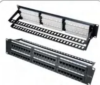 JZ-P5648S-C6A 48-Port Cat6A Shielded Patch Panel 10GBASE-T shielded panel with high port density. View details
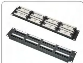 JZ-P2612L-C6 24-Port Cat6 Patch Panel Unitary PCB patch panel tested to ISO/IEC 11801 and TIA/EIA-568-C. View details
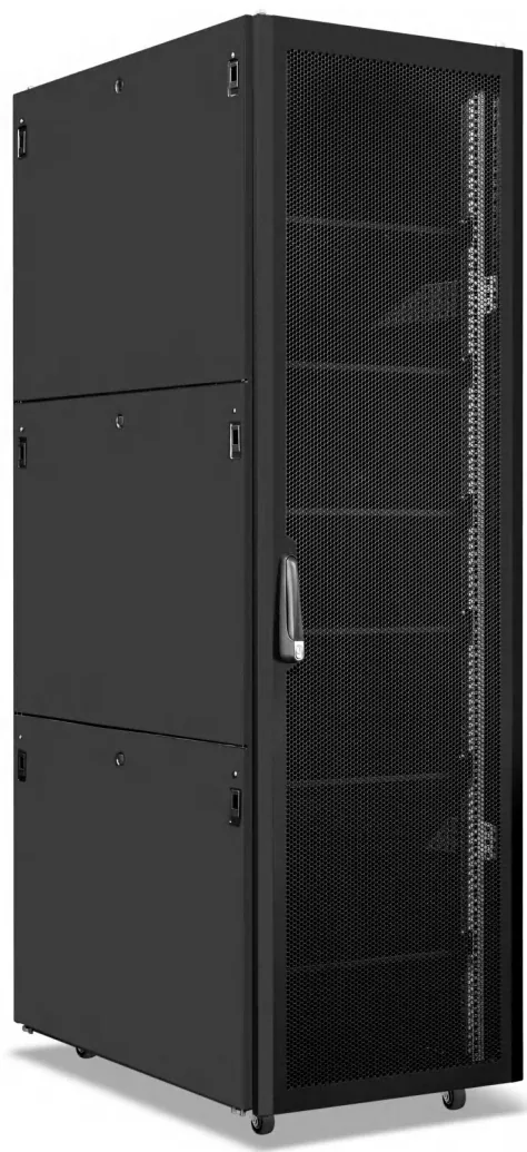 JZ-SC Series 42U Server Cabinet A 1200 mm deep, high-load frame for rack servers and GPU nodes. View details
Need this configured for your project?
Send the rack elevation, power load and quantity. We will confirm dimensions, outlet types and lead time.
Get a Quote